Any design project for a water transport or distribution network is based on the determination of a need for hydraulic supply (Qh) at one or several consumption points.
In the case of transport between two points, there will be a need for a certain flow at the outlet point that matches the flow along the entire network (Qt). However, in the case of a distribution network with several consumption points, there will be different flow rates along the network depending on the mesh, flow rates and consumption points (Q1, Q2,…Qn).
The calculation of the hydraulic need will be done in different ways depending on the type of consumption points in which they will be used.
The flow rates obtained at the consumption points (Qn) will be determined by the pressures at those points before the regulation elements. For this reason, it will be necessary to place the required regulation elements for such flows (irrigation emitters, spray sockets, valves, control valves, etc.). If the highest possible flow rate is to be obtained, no regulation element will be fitted (free outlet) and it will be determined only by the pipes and the outlet section, plus the network pressure differences.
Selection of diameters
Initial considerations and definitions
In the hydraulic calculations of the pipes, whenever there are generic references to the diameter of a pipe, it must be understood that they refers to the inner diameter (ID), as it conditions the transport capacity. Then, we can conclude that the hydraulic dimensioning of the pipe is given by the determination of the diameter.
Some basic concepts related to the selection of the pipes’ diameter are:
- Inner diameter (ID). Average inner diameter of the pipe in any section.
- Outside diameter (OD). Average outside diameter of the pipe in any section.
- Nominal diameter (DN). Value taken from a series of conventional numbers adopted to characterise the dimensions of the diameters and which usually coincides approximately with its actual value in millimetres.
Both concepts, “inner diameter” (ID) and the “outside diameter” (OD) can generally be used. However, it must be taken into account that when we simply talk about nominal diameter (DN), we can be referring both to the inner diameter and the outside diameter depending on the type of pipe. While for ductile iron, concrete and GFRP pipes it refers to the inner diameter, in the case of PVC-U, PP, PE and TOM® PVC-O pipes it refers to the outside diameter.
Recommended speeds
The hydraulic dimensioning is given by the determination of the diameter since the internal diameter (ID) condition the pipes’ transport capacity.

Where:
- v: water flow speed in m/s
- ID: inner diameter of the pipe in m
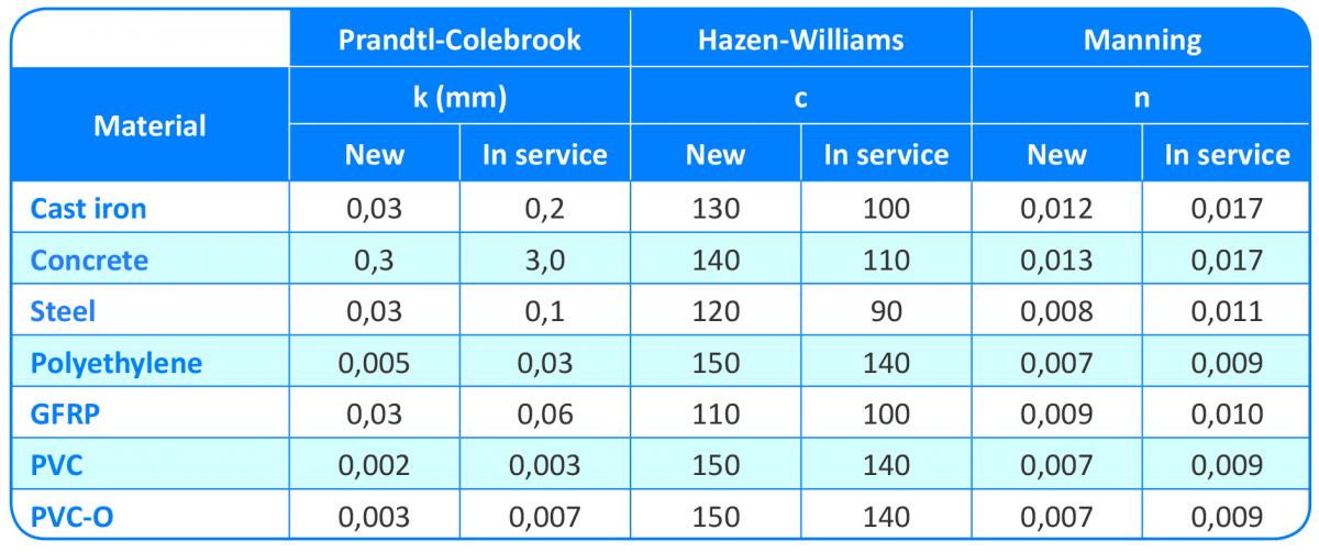
- n: Manning coefficient (for PVC-O, n = 0.007 for a new pipe and n = 0.009 for a pipeline in service)
Prandtl-Colebrook-White, Hazen-Williams and Manning coefficients

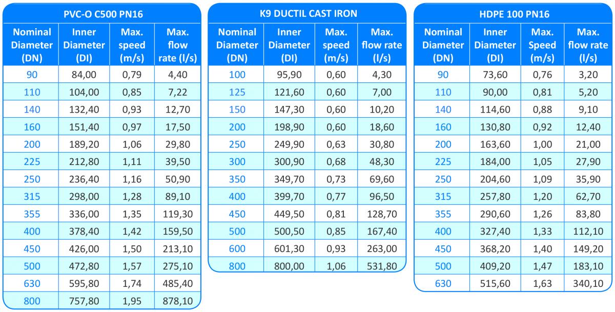
The following table shows a comparison between the maximum recommended speeds of the full range of TOM® PVC-O pipes C500 PN16, Cast iron K9 and PE100 PN16:


