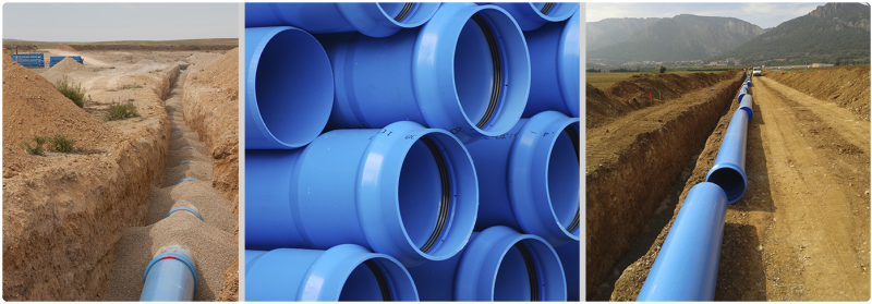
The main purpose of the hydraulic dimensioning of a pipeline is to determine the diameter of the pipe. The basic design conditionings are the required flow rate and the pressure required at the endpoints of the network. In addition to this, other factors such as the design speed or the head losses (continuous and localized) are also involved, as well as the characteristics of the materials of the network (roughness and cost, mainly).
The head loss in a pipe or pipeline is the loss of pressure that occurs in a fluid due to the friction of the fluid particles with each other and against the walls of the pipe that conducts the fluid. Head losses can be continuous, along regular canalizations, or accidental or localized, those due to particular circumstances such as a narrowing, a change of direction, the presence of a valve, etc.
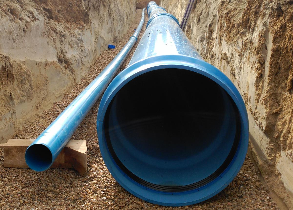
The diameter of a TOM® PVC-O pipeline for the conveyance of water under pressure is determined taking into account:
- - Hydraulic parameters (flow rate, head loss and speed) for gravity systems.
- - Optimal hydraulic and economic parameters (cost of pumping and amortization of facilities) for pumping systems.
- - Depending on the service conditions, the risk of water hammer, cavitation and abrasion must be calculated and the appropriate protections installed.
1- A gravity conduction appears when the elevation of the water in the supply source is higher than the required or existing pressure head height at the water delivery point.
In this case the transport of the fluid is achieved by the available energy difference, that is to say, the existing topography is used so that the conduction is carried out without the need of pumping, thus reaching an acceptable level of pressure.
The formula relating the flow rate with the fluid speed is the following:

- Q: flow rate according to the needs, in l/s.
- v: water speed in the canalization, in m/s.
- DI: inner diameter of the canalization, in m.
To calculate continuous head losses it is recommended to use the universal expression of Darcy-Weisbach:
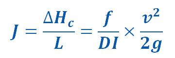
- J: continuous head loss, per unit of length, in m/m
- v: water flow speed in m/s
- ΔHc: continuous head loss, in m
- L: length of the section, in m
- DI: inner diameter of the pipe, in m
- g: acceleration of gravity, in m/s²
- f: head loss coefficient per unit of length (or coefficient of friction), dimensionless
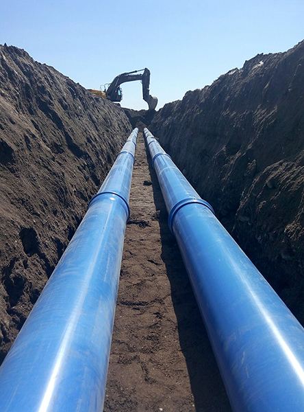
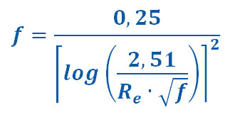
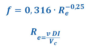
Since PVC-O pipes are completely smooth, the head loss coefficient or energy per unit of length (f) calculus that appears in the Darcy-Weisbach formula can be calculated using the following empirical expressions:
- Prandtl-Colebrook-White:
- Blasius:
- v: water flow speed in m/s
- c: Hazen-Williams roughness coefficient (in the case of TOM® PVC-O pipes, C = 150 for new pipelines and C = 140 for pipelines in service)
- ID: inner diameter of the pipe, in m
- J: continuous head loss per unit of length, in m/m
- Ka: absolute roughness in m (for TOM® PVC-O pipes ka = 0.003∙10-3 m for new pipelines and ka = 0.007∙10-3 m for pipelines in service)
- n: Manning roughness coefficient. In the case of TOM® PVC-O pipes, n = 0.007 for new pipelines and n = 0.009 for pipelines in service
- f: head loss coefficient per unit of length (or coefficient of friction), dimensionless
- Re: Reynolds number, dimensionless
- vc: kinematic viscosity in m2/s (1.01 x10⁻⁶, for water at 20 °C)
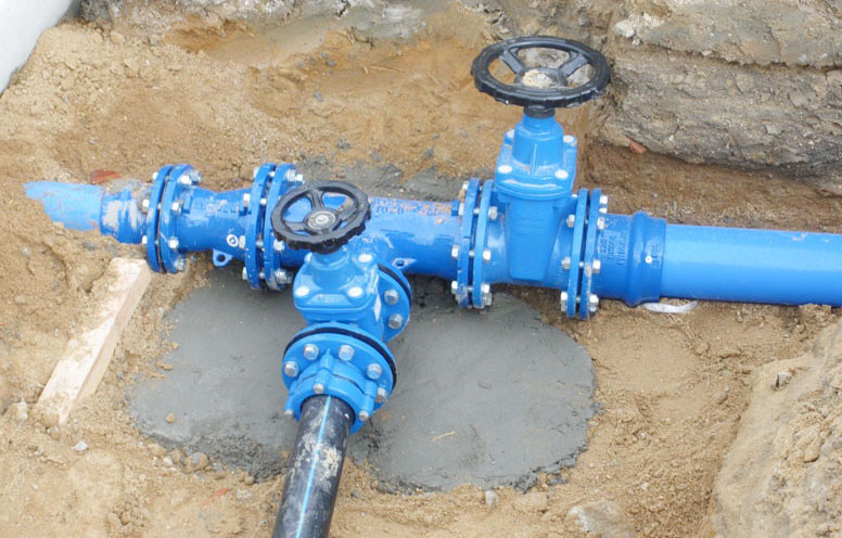
In addition to continuous head losses due to friction, it is necessary to calculate the localized head losses (ΔHl) of the fittings, which will be significant if the fittings are numerous or if the pipe is relatively short. These head losses can be evaluated as a kl fraction of the V2/2g term or as an equivalent length. The K coefficient is dimensionless and depends on the uniqueness and average speed inside the pipe.
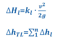
Therefore, the expression for calculating total head loss would be as follows:

On the other hand, the pumping transport system is needed when it is necessary to add energy to obtain the design flow rate. This system is generally used when the water elevation at the supply source is lower than the required pressure head at the water delivery point. In this case, the pumping equipment provides the necessary power to transport the water.
The main information that must be known is the flow of water to be transported and depending on this value, the optimum economic solution for the project will be determined.
The other factors that come into play are: the diameter of the pipe (DI), the conduction speed, the head loss produced by that speed, the pressure at the point of supply and the necessary power of the motor pump unit.
The flow rate (Q), head loss coefficient (J), continuous head loss (ΔHc) and localized head loss (ΔHTL) concepts are equally applicable in the case of a pumping system.

The extremely smooth inner surface of the plastic pipes (less internal roughness) and the absence of incrustations in this material, allow a reduction of the head losses, and therefore, with equal inner diameter, a greater transportable flow with the same energy. It should also be noted that due to their lower adhesion, they allow the useful hydraulic section of the pipe to remain constant throughout its useful life.
The internal smoothness of plastic pipes has been highlighted as one of the main advantages in its use. Its low coefficient of absolute roughness produces unitary load losses of the fluids circulating through them, much lower than those produced in other traditional materials with greater roughness.


